Sunday 23 February 2014

The control panel (part 7) - attaching the control panel to the cabinet

So in the Janaury blog I mentioned the control panel was nearing completion but that I had to figure out how to secure the panel to the actual cabinet.

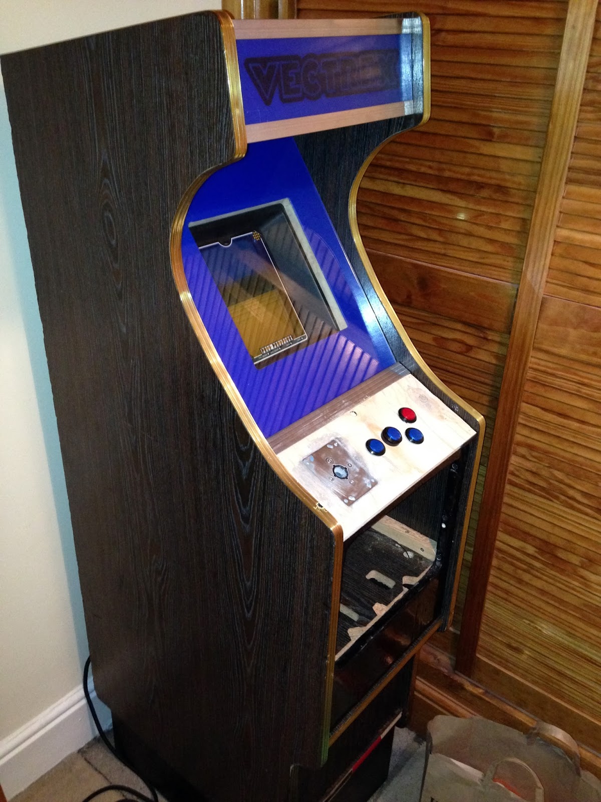
The cabinet did already  provide provision for securing the control panel in the form of two angle brackets each with a hole for threading through a securing bolt. The original control panel had two bolts (with the head embedded in the panel) at either side. The control panel then fits into place with the bolts passing through the holes. Wing nuts are then screwed in place so everything is a tight fit.

I like this approach because  the embedded bolts are not visible from the top of the panel, and using wing nuts mean that should it be necessary to remove the panel it can be simply done when opening the coin mechanism door.

So I used this approach for the VecCab control panel. It did require complete dissassembly of the VecCab control panel so I could add the embedded bolts. The image below shows the top side of the control panel. You can make out the two bolts at either side of the panel. The bolt heads are in countersunk holes and do not stand proud of the wooden panl surface. I added a bit of glue to the bolt heads to ensure the bolts do not move. All of this will be hidden when the final Perspex panel is on top.


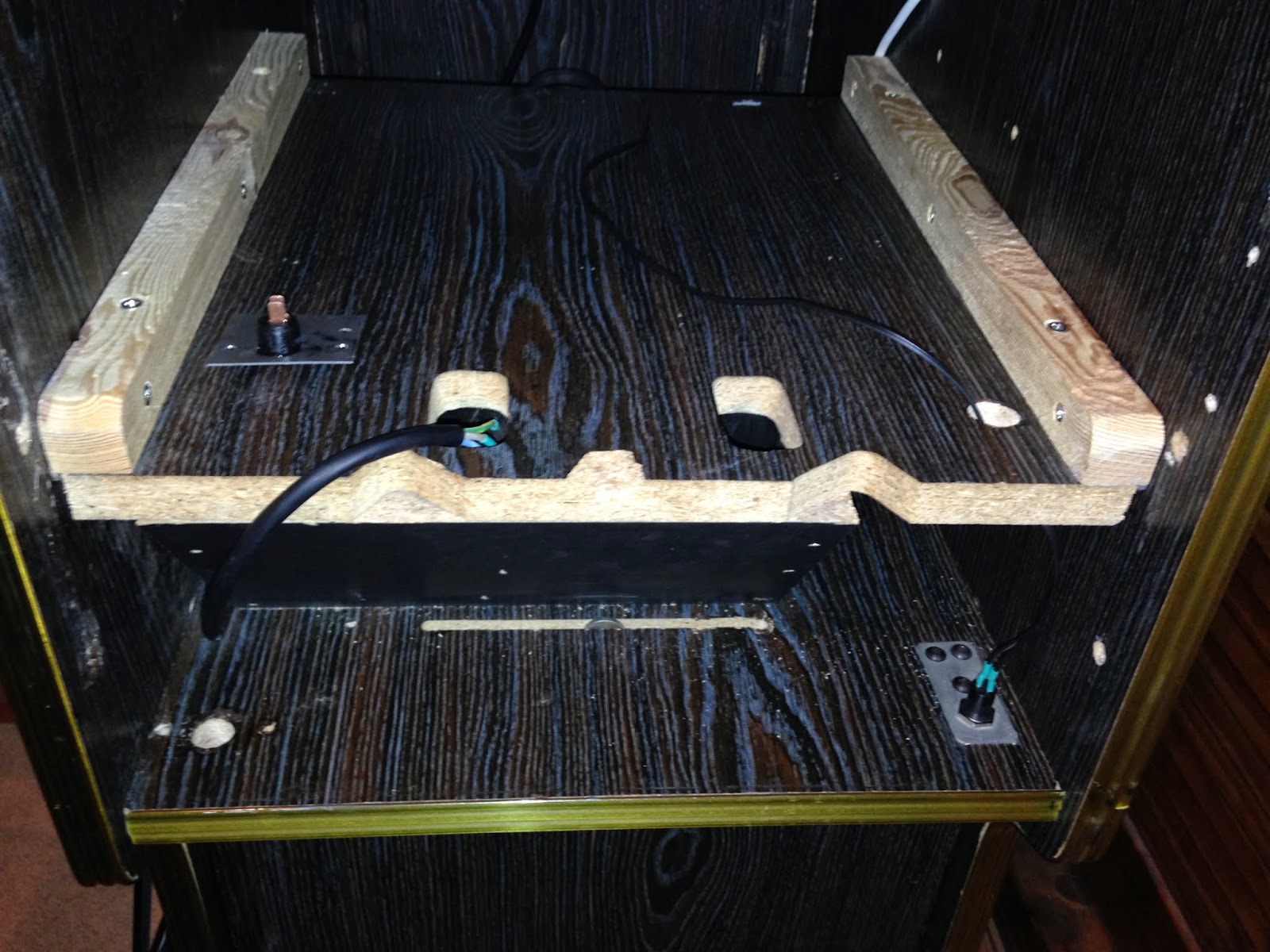
The following image shows the underside of the control panel. You can see the bolts with the wing nuts. Of course the wing nuts are actually fastened to the bolts after the bolts are threaded through the angle brackets on the cabinet. You can also see  a couple of black boxes I have added on the underside. One box will house the electronics which will be responsible for taking the button  and joystick control signals and feeding them to the Vectrex controller port. The other box will house the electronics for proving power the lights that will be embedded in the buttons. To begin with, I will arrange for the lights to be continuiously on - but later I want to switch on and off the lights when coins have been paid - e.g. flashing buttons to act as an attract mode.
The final image shows the control panel on the VecCab and with the buttons and joystick base added.

Nearly there now, all that remains is to wire up the control panel. I'll blog this as soon as it is ready. Then after that you may not be hearing from me because I'll be playing Vectrex games via the VecCab!


Wednesday 12 February 2014

Its alive!

Today I show the mains layout used in the cabinet. In the last blog news I talked about two switches to turn on and off the cabinet. The switch at the rear is a pre-exisiting one, whilst the one at the front is a hidden one only for those in the know! The idea being that the VecCab could be placed in a real amusement arcade and not be at risk from rogue persons who like to switch things off. Of course for the home user, knowing about that secret front switch (and hidden reset button)  is very handy. The following diagram shows the VecCab  mains electricity diagram.

I could have just used a junction box or terminal bock and wired the Vectrex and marquee light directly in. But I think its sacrilege to cut off plugs. Therefore instead I purchased a  four way adaptor from Clas Ohlson and mounted it inside the cabinet. It is easy then to plug in what you want. I did buy a small junction box, but this was used just to connect the other wires together and keep everything tidy.

I took the cord off the four way adaptor, soldered some terminal spades to the wires, added heat shrink and mounted to two of the terminals on the mains switch at the rear. This mains switch is recessed at the back and mounted on a metal plate, so I took care to earth the metal plate. The following image shows the metal plate and mains switch detached from the cabinet:

Next I mounted the main switch and metal plate back in the recessed hole at the base of the rear of the cabinet. I took new wires of the-is rear mains switch into a junction box. The secret front mains switch is wired in series with the live signal and connected to the four way adaptor.

The following iamge shows what can be seen when the rear door of the cabinet is removed:
 

And an image of the back of the cabinet when the rear door is secured:
You can see that its still got the original stickers on, when the cabinet used to earn its living back in the 80's! The stickers are a bitt tatty but for now I'll leave them on, just to make the cabinet look more real.


Secret on/off switch and reset button

Now that the cabinet is starting to take shape I remembered to add a couple  "nice to have"  features that I wanted to include.
 
Readers of the earlier entries in this blog will know  that my goal is to make an arcade cabinet that would not look out of place  in an 80's arcade. However, I have to also balance those requirements with making  a machine that can be also  used conveniently in my living room (if my girlfriend permits it!)


For living room playing I would like to provide  a reset button in order to reset any games (also useful for getting to the main menu in multicarts) and an on/off switch. A suitable push to make push button was procured.

From its JAMMA days the cabinet already included an on/off rocker switch at the bottom of its back. This is fine if the VecCab was going to be in a real arcade. However, for playing in the living room its   not at all convenient to have to delve round the back of the cabinet every time I wanted to turn it on/off.

The on/off switch will control the power to the Vectrex, marquee light, and power supply for the audio amplifier and cabinet lights. I wanted to be sure that I used  a switch that was able to carry enough amps. After much investigation I purchased a ON-OFF Mini Rocker Switch of  the type SPST 10A 250V Car Boat Dash Light Power Snap-in #SW42 from Eltop Electronics on ebay. I selected this because of its physical size and the current carrying ability (it needs to safely switch on/off the Vectrex, marquee lamp, power supply for ancilliary electronics etc.)


For convenient access for the player,   an on/off switch and reset button  must be mounted somewhere on the front of the cabinet. The location has to be convenient to the home user but hidden from the eyeline of a naughty person should they be visiting  the VecCab in an amusement arcade.

Where to place them? Aha, I have placed them underneath and in the area behind  the coin door, the secondary mains switch on the left and the reset button on the right. This is about knee level for an average sized person.

I drilled two 16mm diameter holes into the shelf that supports the vertical coin door panel.  The power switch and push button were mounted on small steel panels and the steel panels screwed down so that the mounted switch and push button partly protrude through the recessof holes. In effect they cannot be seen, as the holes are ressessed.


 In hindsight I should have added these "nice to haves" right from the beginning when I had better access to the supporting  shelf. Because of the limited space it was a struggle to make the small holes to accept the screws which secured the steel panels. I couldn't use a drill. Rather I had to alterante between a PCB track cutter and a drill bit, rotating them inbetween my fingers whilst pressing them down in the vertical direction. This and the fact I also had to use a small screwdriver (as a result no torque)  gave me an enormous blister on my finger!


`
The next two images show the switch and button wired up. For the mains switch plate I made sure it was earthed.The second image clearly shows that the recessed switch and button are not visible.


Now that all remains is for the reset push button to be connected. This means opening up the Vectrex and piggy backing a  couple of wires onto the existing reset button. For the on/off switch this needs to be wired to the power circuitry for the Vectrex, light and other anciliaries.I will cover this in the next blog.