The completed control panel with the underside showing:

The control panel in action:
The completed control panel with the underside showing:
So, I had a bit of an issue with accomodating all the circuity under the control panel when fitting it into the cabinet. The Hall board has the 9 pin d-connector that sticks out the wrong end (for my setup). But the biggest issue is that the screw shaft on the one side of the control panel which feeds into a mounting hole on a 90 degree angled support on the cabinet is too close to the Hall board PCB. This wouldn't have been a problem had I designed the control panel before the Hall board. But the Hall board came after I built the control panel.


So, right from the beginning, I chose backlit arcade buttons. These buttons split into two parts. There's the part that comprises a LED and the actual switch. This inserts into the arcade button housing. These buttons have built-in LEDs. In the olden days, such buttons with flashing lights existed but would have used small filament bulbs.
Interestingly when I bought these (3 blue and 1 red) arcade buttons, the LEDs were not all white light - and didn't rely on the semi transparent arcade button to tint the emitted light colour. The LEDs were actually coloured according to each button colour they were associated with. The blue arcade buttons actually had blue LEDs incorporated, and the red arcade button had a red LED incorporated.

This is an initial photo with all LEDs powered continuously.

But I don't just want them to be contiunuously on. I want them to serve a better purpose which would have worked in a Video arcade hall of the '80s. That is, the buttons would light in particular patterns to attract a passerby to press a button and insert some coins. So the idea is of a sequence of flashing buttons in a "player attract" mode. This is not an original thought. Walk into any casino or sea-side arcade today and you'll see all manner of gambling machines with lights flashing in various patterns and accompanied with weird electronic sounds just enticing you to part with your money.
The VecCab control panel is thus getting a bit more complex now. In addition to Clockworkrobot's Hall board that converts a digital joystick into an analogue one, I'm adding another circuit that will give some intelligence to the control panel.
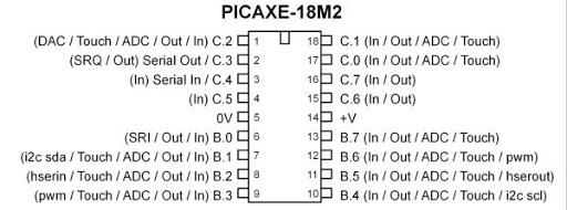
The intelligence is provided by a simple microcontroller. I've chosen a PICAXE18M2 device.These are really simple devices that you can program in a variant of BASIC. Once the program is compiled, it gets tokenised into code that can be downloaded into the microcontroller via a serial interface. I bought a couple of these at a couple of GBP each as I was really curious to see how easy they are to use.
Next step is build the circuit and program....
For those who have stuck with me from the beginning of this blog journey (and boy it's been many years!), you will be familiar with the control panel I've been building for the Vec-Cab project. The setup was originally using an unmodified Sanwa digital joystick.

Now I'm busy converting that digital joystick to an analogue joystick controller using ClockworkRobot's Hall board.

I previously mentioned that the board has plenty of holes in it to support fixing to various joystick configurations. Different joysticks have holes in different places, but through standardisations of Sanwa joystick clones, at least one set of pre-drilled holes should match the location of the joystick holes.
However, there's one specific problem in my use case scenario. That is although I can thread the bolts through the top surface plate of the joystick, it is not then possible to place the black perspex layer directly on top because, the bolt heads stand proud out of the top plate surface.
Therefore, I needed a joystick with holes underneath to which I can thread through the bolts.
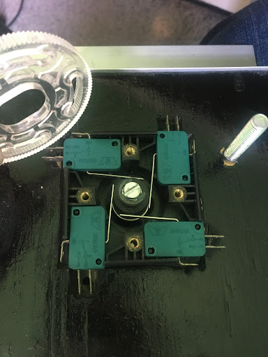
The first thing was to remove the existing restrictor plate and the four micro leaf switches. The leaf micro switches don't have to come out but removing them avoids the clicking sound heard in such digital joysticks. The switches slide out by wiggling in an upward manner. As soon as any gap between the leaf switch and base appears, gently inserting a flat blade screwdriver and levering underneath helps with their removal.


So, in a nutshell, with this converter kit, take a digital arcade joystick, attach the magnet to the joystick shaft, take the provided bolts, thread though existing holes on the joystick, attach nuts to secure bolts to joystick, attach more nuts to suspend the board (shown below) at a specific height over the center of the shaft (with PCB component side facing upwards), arrange for the Hall sensor on the PCB to be within 4 mm of the magnet, add a cable to connect board into player port, and you have analogue joystick control!

So when the joystick shaft is pushed in the forward direction, it swings the magnet in the Southerly direction. Similarly, when pulling the joystick, it swings the magnet in the Northerly direction. When moving the joystick to the left, it swings the magnet to the westerly direction. When moving the joystick to the right, it swings the magnet to Easterly direction.

I just received a Hall board from James Watt aka ClockworkRobot. What is this? I hear you say. This is a fantastic new product by James to covert a digital arcade joystick (Sanwa or clone) into an analogue stick. Since starting my VecCab build I’ve been on a quest to find an affordable analogue arcade joystick that can be used in my setup.
You may ask why being able to play Vectrex games with an analogue joystick is useful when so many games on the Vectrex are configured for digital anyway. Well, this is a valid point, but on the VecCab I am building I want the feel of analogue. I don’t want to hear the click of the switches that you would hear with say a Sanwa digital joystick. In addition, with the Vector Mame Arcade emulators available on the VecFever, the majority are configurable for use with an analogue joystick.
Until now the possible analogue joy stick solutions have been very far and few between. I’ve been eyeing up original and OEM arcade analogue sticks in the past but have been put off from hitting the purchase button because prices were in excess of £200! In an other approach I’ve bought a couple of cheap analogue joysticks intended for some of the 80’s computers with a view to mechanically and electronically modifying (changing the potentiometers resistance to the same variable resistance as the Vectrex ones). However, these sticks have been sitting in a box waiting for that day when I can drum up enough power to overcome my natural procrastination and dedicate time to make a full investigation.
Imagine my joy when I saw James’ idea in the Facebook Vectrex Fan’s unite forum and later demonstrated on YouTube. Like all good ideas, the simplicity of the idea, makes it an immediate winner. It also shortcuts my previous deliberations and investigations into a working solution for an analogue joystick.
The idea is to put a magnet on the end of the existing shaft of the digital joystick and use a Hall effect sensor placed under the shaft to sense the position of the magnet on the joystick shaft with respect to the Hall sensor. When the stick is moved, the magnet moves relative to the static position of the Hall sensor. This then gets converted into a voltage signal that the Vectrex can understand.
James’ Hall solution is a populated PCB (microprocessor onboard) supplied with ancillaries (bolts, nuts and Neodymium magnets) that can easily attach to the underside of a standard Sanwa digital joystick.

After a long hiatus away from the Vec-Cab project I return!
So first step, continue with mounting the Vectrex securely into the cabinet. Early readers will remember I had made a tray for holding the Vectrex and that pivots open to a horizontal position for easy (operator) access or closed in an angled position so the Vectrex sits flush with the external glass.
There's been a change since I considered this all those years ago. That is Laurnence Bennion's Ultraviolet overlays. These overlays and UV light bezel by James Watt combo give the effect of a holographic dimension where depending on the UV light intensity the Vector graphics appear to float either behind or on top of the overlay. I definitely wanted this built into my cabinet.
Therefore to incorporate the UV light bezel, I had to take into account the extra total thickness when the tray holding the Vectrex is closed. The trick was getting the Vectrex and tray to sit completely horizontal when the tray was closed. This took several iterations and new holes to support the tray.
Anyhow, I eventually sorted it out. To finish the tray off I gave the tray a lick of varnish:

The last step was to put in cloth tape into the tray hole that the Vectrex will sit in, just to show the Vectrex an extra bit of love! Hopefully, this should ensure that I don't scratch any Vectrex consoles placed in the tray hole.

