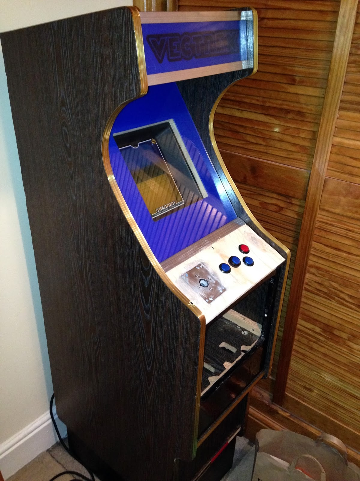
Friday, 9 February 2024

"Other kids on the block"

Scrolling back in the blog you’ll see I have been off and on with the VecCab and Full upright Vectrex arcade using 19” monitor endeavours for quite a few years. Real life takes over, and  Vectrex development tasks get pushed to the back.

I’m still active with the Vectrex Fans Unit Facebook forum, and it’s a good place to be as you get to see the results of other Vectrex mad heads every now and then.

This often sparks me into continuing with my own developments. So fresh for me this week is seeing the images from Herve L’Helgoualch. He’s built a Vectrex arcade cabinet, housing two original controllers – in effect a two-player cabinet.

The cabinet is large, and he has shelves in the available space to store Vectrex games and overlays. The cabinet graphics are fantastic and in keeping with the overall Vectrex flavour. He made the graphics using Adobe Illustrator and printed them out on sticker sheets.

Herve, kindly allowed me to show his images here. He also gave a link which provides a lot of details about the build: Herve's link


Sunday, 16 July 2023

That doesn't look like a normal Vectrex display?

I've had contact from a  YouTuber asking about the Vectrex screen in my VecCab and it not looking like a Vectrex screen.  It looks different to a normal Vectrex screen because I am using Ultraviolet (UV) light to light up a UV-painted overlay placed  in front of the Vectrex display. Not my idea but one I fell in love with when Laurence Bennion of Blacklighter.co.uk came up with UV printed overlays and James Watt of ClockWorkrobot.com started supplying UV flames. The frame gives a bright uniform light around the screen and allows the UV to be used in daylight. You have to see it to believe it but it really adds value to the game graphics. Depending on the brightness of the UV (I can set this by adjusting the power fed into the frame) imagery on the overlay can appear either on front of or behind the Vectors - the effect is almost holographic. In addition, the overlays are multi coloured also contributing to the appearance of multi-coloured Vectors on the Vectrex.

My favourite UV overlay is the "Moon" one as this one goes well with a lot of the Vectrex space-themed games.


The video of the Vectrex can't capture the beauty of the UV overlay and combined graphics but see below:


VecCab up and running!

After a long hiatus due to major house renovations, the house is returning to normality and my Vectrex-related hobbies can resume. Progress was made this weekend in clearing out a room to house the VecCab.

As you can see, it looks pretty good:


Readers who joined me from the beginning of this blog will recall that this cabinet is based on a JAMMA arcade cabinet, and what I did was to get the width of the cabinet reduced, so the small screen of the Vectrex wouldn't look so odd. The sizing works! Sure the Vectrex screen is smaller than a standard arcade cabinet, but the size is more in keeping with what represents a Cabaret cabinet style.

For those interested, here is what the side profile looks like:


I still have many things to work on this project. But it works, and with the VecFever plugged in it's easy to get distracted by playing Vector games rather than making further improvements.

Wednesday, 22 September 2021

Vec-Cab Control Panel finally finished

 The top side of the control panel:


The completed control panel with the underside showing:


The control panel in action:


Monday, 20 September 2021

The creation of Frankenstein

So, I  had a bit of an issue with accomodating all the circuity under the control panel when fitting it into the cabinet. The Hall board has the 9 pin d-connector that sticks out the wrong end (for my setup). But the biggest issue is that the screw shaft on the one side of the control panel which feeds into a mounting hole on a 90 degree angled support on the cabinet is too close to the Hall board PCB.  This wouldn't have been a problem had I designed the control panel before the Hall board. But the Hall board came after I built the control panel.


Not a problem. James Watt designer of the Hall board told me that the hashed area can be drilled in and cut off without risking damage to the PCB circuitry. Of course, cutting off one side of the Hall board which I have done according to the red straight line shown below does mean I lose the button connector. 


What I've done is add a dual in-line 10-way ribbon cable connector and soldered wires to the d-pin connector pads on the Hall board.


Monday, 12 July 2021

Control Panel Enhancements (It's light, Jim, but not as we know it)

So, right from the beginning, I chose backlit arcade buttons. These buttons split into two parts. There's the part that comprises a LED and the actual switch. This inserts into the arcade button housing. These buttons have built-in LEDs. In the olden days, such buttons with flashing lights existed but would have used small filament bulbs.  

Interestingly when I bought these (3 blue and 1 red) arcade buttons, the LEDs were not all white light - and didn't rely on the semi transparent arcade button to tint the emitted light colour. The LEDs were actually coloured according to each button colour they were associated with. The blue arcade buttons actually had blue LEDs incorporated, and the red arcade button had a red LED incorporated.


This is an initial photo with all LEDs powered continuously.

But I don't just want them to be contiunuously on. I want them to serve a better purpose which would have worked in a Video arcade hall of the '80s. That is, the buttons would light in particular patterns to attract a passerby to press a button and insert some coins. So the idea is of a sequence of flashing buttons in a "player attract" mode. This is not an original thought. Walk into any casino or sea-side arcade today and you'll see all manner of gambling machines with lights flashing in various patterns and accompanied with weird electronic sounds just enticing you to part with your money.

The VecCab control panel is thus getting a bit more complex now. In addition to Clockworkrobot's Hall board that converts a digital joystick into an analogue one, I'm adding another circuit that will give some intelligence to the control panel. 

The intelligence is provided by a simple microcontroller. I've chosen a PICAXE18M2 device.These are really simple devices that you can program in a variant of BASIC. Once the program is compiled, it gets tokenised into code that can be downloaded into the microcontroller via a serial interface. I bought a couple of these at a couple of GBP each as I was really curious to see how easy they are  to use.


The idea will be to program it so the fire button (button 4) flashes and after a short while all the buttons flash. As soon as a button is pressed, the PICAXE will know a player is present. The button will then continuously light, or momentarily switch off (haven't decided yet) upon each press. If there is no player interaction with the game via the buttons, after a few minutes, the PICAXE will return to the "player attract" sequence of button flashing. So in action, if you are hitting buttons during game play the "player attract" mode is not visible. When the player walks away, the flashing button sequence starts again. 

Next step is build the circuit and program....


Wednesday, 5 May 2021

Adding analogue functionality to the Vec-Cab control panel (Part 3)

For those who have stuck with me from the beginning of this blog journey (and boy it's been many years!), you will be familiar with the control panel  I've been building  for the Vec-Cab project. The setup was originally using an unmodified Sanwa digital joystick.


Now I'm busy converting that digital joystick to an analogue joystick controller using ClockworkRobot's Hall board.

I previously  mentioned that the board has plenty of holes in it to support fixing to various joystick configurations. Different joysticks have holes in different places, but through standardisations of Sanwa joystick clones, at least one set of pre-drilled holes should match the location of the joystick holes.

However, there's one specific problem in my use case scenario. That is although I can thread the bolts through the top surface plate of the joystick, it is not then possible to place the black perspex layer directly on top because, the bolt heads stand proud out of the top plate surface.

Therefore, I needed a joystick with holes underneath to which I can thread through the bolts. 

The first thing was to remove the existing  restrictor plate and the four micro leaf switches. The leaf micro switches don't have to come out but removing them avoids the clicking sound heard in such digital joysticks. The switches slide out  by wiggling in an upward manner. As soon as any gap between the leaf switch and base appears, gently inserting a  flat blade screwdriver and levering underneath helps with their removal.


Next, I wanted to add a new plate that would fit onto the remaining joystick mount. I got a spare plate from an old (non Sanwa) joy stick I had lying around. I drilled four new holes in the plate so that they would align with the mount holes previously used for securing the restrictor plate. I also placed and secured four bolts into the corner holes. These bolts will feed into four matching located and freshly drilled holes in the ClockworkRobot Hall board. The top nuts are used to ensure that the Hall sensor on the PCB is spaced not more than 4 mm distance from the magnet.


I cut off one of the plastic prongs protruding from the plate as when the Hall board was placed on top, the prong was interfering with the micro-controller on the Hall board.

I took the smallest of the two magnets supplied in the Hall board kit and attached to the bottom of the joystick shaft. 

!!! WARNING !!! TAKE CARE WHEN HANDLING THE MAGNETS. DONT BRING THE TWO TOGETHER AS THEY ARE VERY STRONG AND COULD TRAP YOUR SKIN IN-BETWEEN!

For testing purposes and if you are gentle in your game play, just using magnet power to secure the magnet to the shaft is enough. However, to make a permanent mechanical connection you should dab some Araldite glue between the magnet and the shaft.


Drill four new holes into the Hall board. The holes must align with the location of the bolts located at each corner of the joystick plate. If you make the holes bigger than the M4 bolt diameter it gives you the ability to twist the Hall board if necessary to ensure the Hall sensor is well aligned with the centre of the magnet.


You can actually drill anywhere in the hashed area without fear of destroying any conducting layers (see my new holes made in the inside drawn square below).


Finally, drop the Hall board over the bolts and screw on the nuts to secure. Make sure the PCB components are on the underside.


The next step is testing.....


Tuesday, 4 May 2021

The joys (tick) of analogue (part 2)

So, in a nutshell, with this converter kit, take a digital arcade joystick, attach the magnet to the joystick shaft, take the provided bolts, thread though existing holes on the joystick, attach nuts to secure bolts to joystick, attach more nuts to suspend the board (shown below) at a specific height over the center of the shaft (with PCB component side facing upwards), arrange for the Hall sensor on the PCB to be within 4 mm of the magnet, add a cable to connect board into player port, and you have analogue joystick control!

So when the joystick shaft is pushed in the forward direction, it swings the magnet in the Southerly direction. Similarly, when pulling the joystick, it swings the magnet in the Northerly direction. When moving the joystick to the left, it swings the magnet to the westerly direction. When moving the joystick to the right, it swings the magnet to Easterly direction. 


The above is just an example with a pretty non-descript joystick I found lying around. I'll go into more detail in  a later post regarding the specific joystick to be used in my VecCab.


Finally, an analogue arcade joystick solution (Part 1)

I just received a Hall board from James Watt aka ClockworkRobot. What is this? I hear you say. This is a fantastic new product by James  to covert a digital arcade joystick (Sanwa or clone) into an analogue stick. Since starting my VecCab build I’ve been on a quest to find an affordable analogue arcade joystick that can be used in my setup.

You may ask why being able to play Vectrex games with an analogue joystick is useful when so many games on the Vectrex are configured for digital anyway. Well, this is a valid point, but on the VecCab I am building I want the feel of analogue. I don’t want to hear the click of the switches that you would hear with say a Sanwa digital joystick. In addition, with the Vector Mame Arcade emulators available on the VecFever, the majority are configurable for use with an analogue joystick.

Until now the possible analogue joy stick solutions have been very far and few between. I’ve been eyeing up original and OEM arcade analogue sticks in the past but have been put off from hitting the purchase button because prices were in excess of £200! In an other approach I’ve bought a couple of cheap analogue joysticks intended  for some of the 80’s computers with a view to mechanically  and electronically modifying (changing the potentiometers resistance  to the same variable resistance as the Vectrex ones). However, these sticks  have been sitting in a box waiting for that day when I can  drum up enough power to overcome my natural procrastination and dedicate  time to make a full investigation.

Imagine my joy when I saw James’ idea in the Facebook Vectrex Fan’s unite forum and later demonstrated on YouTube. Like all good ideas, the simplicity of the idea, makes it an immediate winner. It also shortcuts my previous deliberations and investigations into a working solution for an analogue joystick. 

The idea is to put a magnet on the end of the  existing shaft of the digital joystick and use a Hall effect sensor placed under the shaft  to sense  the position of the magnet on the joystick shaft with respect  to the Hall sensor. When the stick is moved, the magnet moves relative to the static position of the Hall sensor. This then gets converted into a voltage signal that the Vectrex can understand.

James’ Hall solution  is a populated PCB (microprocessor onboard) supplied with ancillaries (bolts, nuts and Neodymium magnets) that can easily attach to the underside of a standard Sanwa digital joystick.

The Hall board digital to analogue arcade stick converter kit as received from ClockworkRobot.com


Saturday, 20 February 2021

Vec-Cab continues

 After a long hiatus away from the Vec-Cab project I return!

So first step, continue with mounting the Vectrex securely into the cabinet. Early readers will remember I had made a tray for holding the Vectrex and  that pivots open to  a horizontal position for easy (operator) access or closed in an angled position so the Vectrex sits flush with the external glass.

There's been a change since I considered this all those years ago. That is Laurnence Bennion's Ultraviolet overlays. These overlays and UV light bezel by James Watt combo give the effect of a holographic dimension where depending on the UV light intensity the Vector graphics appear to float either behind or on top of the overlay. I definitely wanted this built into my cabinet.

Therefore to incorporate the UV light bezel, I had to take into account the extra total thickness when the tray holding the Vectrex is closed. The trick was getting the Vectrex and tray to sit completely horizontal when the tray was closed. This took several iterations and new holes to support the tray.

Anyhow, I eventually sorted it out. To finish the tray off I gave the tray a lick of varnish:

The last step was to put in cloth tape into the tray  hole that the Vectrex will sit in, just to show the Vectrex an extra bit of love! Hopefully, this should ensure that I don't scratch any Vectrex consoles placed in the tray hole.


The final result with the tray secured in the cabinet and a Vectrex in place:


It's starting to come together...

Monday, 16 April 2018

More inspiration!

Wow, hot on the heals of the Vect-Rex Vectrex arcade cabinet by "Guys, Games and beers", Jason Kopp has also  built a Vectrex based  full arcade upright and this one uses a colour vector monitor!

Of course Vectrex games were never designed from the beginning to have colour  other than through pseudo colour using coloured overlays. However, Jason as built some electronics that generates different colours on a colour Vector monitor  according to Vectrex brightness. As a result some of the standard Vectrex  games already look pretty good as a result of the colour mod and with no change to the program code. New home brews should be able to take advantage of the relatively simple programming (through change in Vector brightness) required to generate colour to make even more impressive colour displays.

For those lucky ones who attended the Midwest Gaming Classic trade show, Milwaukee, USA,  this weekend gone, they got to see and play  both this and the Vect-Rex.


The bar has been set!

Sunday, 1 April 2018

I’ve just seen it was February 2014 that I made my last blog entry!  The Vec-Cab reached 65% completion and then other projects became more interesting.

But it’s amazing how priorities can change because of a chance encounter, and as such I now officially re-open this blog to continue documenting my endeavours for creating an upright Vectrex cabinet J

The chance encounter was seeing the video from the collective known as "Guys, Games and Beer". They have developed a full size Vectrex upright cabinet with a 19 inch monitor and it looks beautiful. 


“Guys, Games and Beer” informed  that they were inspired by the work of Jason Kopp aka Arcade Jason.
In the last quarter of last year Jason posted a couple of  YouTube videos where he had taken a 19 and 23 inch vector arcade monitors and converted them for use with the Vectrex. At the time I  was also captivated by the thought of a 19 inch monitor for displaying Vectrex games and purchased a spare monitor Jason had found end of last year. This monitor would be too big (wide) to fit in my Vec-Cab, but already in my mind were thoughts about a bigger sister cabinet to house this monitor.

Unfortunately, the courier(s) had been rather unkind to the package USA to UK travels and I received a half open box from the post office and a letter saying the delivery had been damaged. Early attempts at getting a  correct picture were not successful. 


The vector beam was shown at full brightness and I could not turn it down – this meant that all the vector drawing was visible.  This project is on hold until I have more dialogue with Jason - but as and when there is a postive update I will report here.


Anyway, back to the “Guys, Games and Beer” system which they call Vect-Rex. They took an old cabinet and mounted in it a 19 inch monitor in vertical orientation linked to a Vectrex with multi-cart. Vect-Rex is a standard size cabinet so they could fit a two player control panel.


The most ingenious thing about the Vect-Rex cabinet is how the overlays are changed according to the game being played. This is achieved by a scrolling overlay. Basically, a number of enlarged overlays have been printed on a roll of transparent sheet. Through markings on the sheet and use of a light sensing sensor, the roll is advanced in the upward or downward direction on motorised rollers. A button corresponding to up or down needs to be pressed to advance the roll one overlay at a time. 


Thanks "Guys, Games and Beer", you’ve given me a push to continue with my VecCab developments.

Sunday, 23 February 2014

The control panel (part 7) - attaching the control panel to the cabinet

So in the Janaury blog I mentioned the control panel was nearing completion but that I had to figure out how to secure the panel to the actual cabinet.

The cabinet did already  provide provision for securing the control panel in the form of two angle brackets each with a hole for threading through a securing bolt. The original control panel had two bolts (with the head embedded in the panel) at either side. The control panel then fits into place with the bolts passing through the holes. Wing nuts are then screwed in place so everything is a tight fit.

I like this approach because  the embedded bolts are not visible from the top of the panel, and using wing nuts mean that should it be necessary to remove the panel it can be simply done when opening the coin mechanism door.

So I used this approach for the VecCab control panel. It did require complete dissassembly of the VecCab control panel so I could add the embedded bolts. The image below shows the top side of the control panel. You can make out the two bolts at either side of the panel. The bolt heads are in countersunk holes and do not stand proud of the wooden panl surface. I added a bit of glue to the bolt heads to ensure the bolts do not move. All of this will be hidden when the final Perspex panel is on top.


The following image shows the underside of the control panel. You can see the bolts with the wing nuts. Of course the wing nuts are actually fastened to the bolts after the bolts are threaded through the angle brackets on the cabinet. You can also see  a couple of black boxes I have added on the underside. One box will house the electronics which will be responsible for taking the button  and joystick control signals and feeding them to the Vectrex controller port. The other box will house the electronics for proving power the lights that will be embedded in the buttons. To begin with, I will arrange for the lights to be continuiously on - but later I want to switch on and off the lights when coins have been paid - e.g. flashing buttons to act as an attract mode.
The final image shows the control panel on the VecCab and with the buttons and joystick base added.

Nearly there now, all that remains is to wire up the control panel. I'll blog this as soon as it is ready. Then after that you may not be hearing from me because I'll be playing Vectrex games via the VecCab!


Wednesday, 12 February 2014

Its alive!

Today I show the mains layout used in the cabinet. In the last blog news I talked about two switches to turn on and off the cabinet. The switch at the rear is a pre-exisiting one, whilst the one at the front is a hidden one only for those in the know! The idea being that the VecCab could be placed in a real amusement arcade and not be at risk from rogue persons who like to switch things off. Of course for the home user, knowing about that secret front switch (and hidden reset button)  is very handy. The following diagram shows the VecCab  mains electricity diagram.

I could have just used a junction box or terminal bock and wired the Vectrex and marquee light directly in. But I think its sacrilege to cut off plugs. Therefore instead I purchased a  four way adaptor from Clas Ohlson and mounted it inside the cabinet. It is easy then to plug in what you want. I did buy a small junction box, but this was used just to connect the other wires together and keep everything tidy.

I took the cord off the four way adaptor, soldered some terminal spades to the wires, added heat shrink and mounted to two of the terminals on the mains switch at the rear. This mains switch is recessed at the back and mounted on a metal plate, so I took care to earth the metal plate. The following image shows the metal plate and mains switch detached from the cabinet:

Next I mounted the main switch and metal plate back in the recessed hole at the base of the rear of the cabinet. I took new wires of the-is rear mains switch into a junction box. The secret front mains switch is wired in series with the live signal and connected to the four way adaptor.

The following iamge shows what can be seen when the rear door of the cabinet is removed:
 

And an image of the back of the cabinet when the rear door is secured:
You can see that its still got the original stickers on, when the cabinet used to earn its living back in the 80's! The stickers are a bitt tatty but for now I'll leave them on, just to make the cabinet look more real.


Secret on/off switch and reset button

Now that the cabinet is starting to take shape I remembered to add a couple  "nice to have"  features that I wanted to include.
 
Readers of the earlier entries in this blog will know  that my goal is to make an arcade cabinet that would not look out of place  in an 80's arcade. However, I have to also balance those requirements with making  a machine that can be also  used conveniently in my living room (if my girlfriend permits it!)


For living room playing I would like to provide  a reset button in order to reset any games (also useful for getting to the main menu in multicarts) and an on/off switch. A suitable push to make push button was procured.

From its JAMMA days the cabinet already included an on/off rocker switch at the bottom of its back. This is fine if the VecCab was going to be in a real arcade. However, for playing in the living room its   not at all convenient to have to delve round the back of the cabinet every time I wanted to turn it on/off.

The on/off switch will control the power to the Vectrex, marquee light, and power supply for the audio amplifier and cabinet lights. I wanted to be sure that I used  a switch that was able to carry enough amps. After much investigation I purchased a ON-OFF Mini Rocker Switch of  the type SPST 10A 250V Car Boat Dash Light Power Snap-in #SW42 from Eltop Electronics on ebay. I selected this because of its physical size and the current carrying ability (it needs to safely switch on/off the Vectrex, marquee lamp, power supply for ancilliary electronics etc.)


For convenient access for the player,   an on/off switch and reset button  must be mounted somewhere on the front of the cabinet. The location has to be convenient to the home user but hidden from the eyeline of a naughty person should they be visiting  the VecCab in an amusement arcade.

Where to place them? Aha, I have placed them underneath and in the area behind  the coin door, the secondary mains switch on the left and the reset button on the right. This is about knee level for an average sized person.

I drilled two 16mm diameter holes into the shelf that supports the vertical coin door panel.  The power switch and push button were mounted on small steel panels and the steel panels screwed down so that the mounted switch and push button partly protrude through the recessof holes. In effect they cannot be seen, as the holes are ressessed.


 In hindsight I should have added these "nice to haves" right from the beginning when I had better access to the supporting  shelf. Because of the limited space it was a struggle to make the small holes to accept the screws which secured the steel panels. I couldn't use a drill. Rather I had to alterante between a PCB track cutter and a drill bit, rotating them inbetween my fingers whilst pressing them down in the vertical direction. This and the fact I also had to use a small screwdriver (as a result no torque)  gave me an enormous blister on my finger!
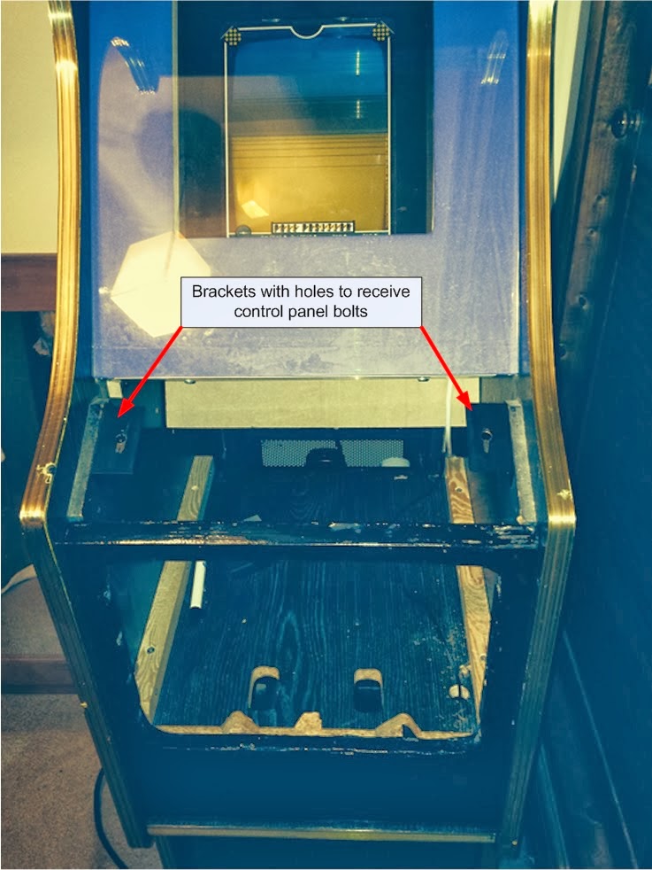


`
The next two images show the switch and button wired up. For the mains switch plate I made sure it was earthed.The second image clearly shows that the recessed switch and button are not visible.


Now that all remains is for the reset push button to be connected. This means opening up the Vectrex and piggy backing a  couple of wires onto the existing reset button. For the on/off switch this needs to be wired to the power circuitry for the Vectrex, light and other anciliaries.I will cover this in the next blog.